EN
EN
 AR
AR
 BG
BG
 CS
CS
 DA
DA
 NL
NL
 FI
FI
 FR
FR
 DE
DE
 EL
EL
 HI
HI
 IT
IT
 JA
JA
 KO
KO
 NO
NO
 PL
PL
 PT
PT
 RU
RU
 ES
ES
 SV
SV
 TL
TL
 ID
ID
 UK
UK
 VI
VI
 HU
HU
 TH
TH
 TR
TR
 FA
FA
 AF
AF
 MS
MS
 SW
SW
 GA
GA
 CY
CY
 BE
BE
 KA
KA
 LA
LA
 MY
MY
 TG
TG
 UZ
UZ


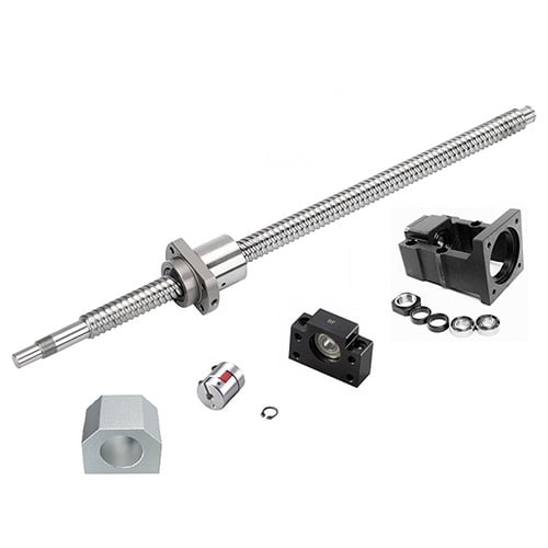
When engineers specify ball screws for all-electric injection molding machines, most attention goes to the screw diameter, lead, and nut type. But the support bearing configuration at the screw ends is equally critical — it determines axial rigidity, critical speed, thermal growth behavior, and ultimately the machine's positioning performance.
A poorly chosen bearing setup causes vibration at high speeds, excessive thermal stress, and premature failure. This guide breaks down the four standard support configurations and explains which one to use for each axis of an injection molding machine.
Why Support Bearings Matter
Ball screws are long, slender shafts under axial load. Without proper end support, they suffer from two fundamental problems:
1. Axial deflection under load
When the screw pushes or pulls a load, the shaft itself compresses or stretches elastically. This directly reduces positioning accuracy. Support bearings must resist this axial movement with maximum rigidity.
2. Lateral vibration (whirling) at high speed
As screw RPM increases, centrifugal forces cause the shaft to bow outward — a phenomenon called "screw whirl" or "ball screw whirling." At the critical speed, vibration becomes severe enough to damage the nut, bearings, and screw shaft itself. Support bearing type and span directly determine the critical speed.
In injection molding, both issues matter:
- Clamping axes: High axial load → rigidity is critical
- Injection axes: High speed + moderate load → both rigidity and critical speed matter
- Ejection axes: Medium speed, low load → cost-effective standard solutions work well
The Four Standard Support Configurations
1. Fixed-Free (Cantilever)
Description: One end is supported by a fixed bearing set (angular contact or thrust bearings); the other end has no support at all.
Rigidity: Lowest — the screw acts like a cantilever beam
Critical speed: Lowest — only about 15% of fixed-supported
Thermal growth: Free end allows expansion without constraint
Cost: Lowest
Where it's used:
- Very short stroke applications
- Vertical axes where the screw hangs down
- Light-load, low-speed applications
Injection molding application:
Rarely used on main axes. Sometimes found on small auxiliary axes like nozzle touch on micro-molders. Not recommended for any primary axis.
2. Supported-Supported (Simply Supported)
Description: Both ends have radial support bearings (deep groove ball bearings) that locate the screw radially but allow axial float.
Rigidity: Low — no axial constraint
Critical speed: Moderate — both ends supported radially
Thermal growth: Both ends can float axially, so thermal expansion is fully free
Cost: Low
Where it's used:
- Transport axes and conveyors
- Low-precision positioning
- Applications where thermal growth is the primary concern
Injection molding application:
Not suitable for precision axes. The complete lack of axial rigidity makes accurate positioning impossible.
3. Fixed-Supported (Most Common)
Description: One end has a fixed bearing set (angular contact bearings, duplex or triplex mounted) that resists both radial and axial loads. The opposite end has a simple radial support bearing that allows axial float.
Rigidity: High — fixed end provides axial location
Critical speed: High — both ends radially supported
Thermal growth: Free end accommodates expansion toward the supported side
Cost: Moderate
Where it's used:
- Most general-purpose positioning applications
- Medium-to-high speed axes
- Applications with significant temperature variation
Injection molding application:
This is the standard configuration for most injection axes. The fixed end is mounted at the drive/motor side; the supported end floats to accommodate thermal growth. This balances rigidity, speed capability, and thermal management.
4. Fixed-Fixed (Both Ends Rigid)
Description: Both ends have fixed bearing sets (angular contact bearings preloaded against each other), fully constraining the screw axially at both ends.
Rigidity: Highest — axial constraint at both ends doubles effective stiffness
Critical speed: Highest — up to 4× higher than fixed-free
Thermal growth: Fully constrained → thermal expansion becomes compressive stress
Cost: Highest — more bearings, more complex assembly, requires preload adjustment
Where it's used:
- Ultra-high precision machine tools
- High-speed, high-acceleration axes
- Applications requiring maximum rigidity
Injection molding application:
Used on high-precision clamping axes of large all-electric machines where maximum rigidity is essential. The trade-off is that thermal growth is constrained, creating internal compressive forces. This requires either cooled screws, very tight temperature control, or careful bearing preload calculation to avoid overloading.
Configuration Selection by Injection Molding Axis
Clamping Axis
Recommended: Fixed-Supported (standard) or Fixed-Fixed (high-precision)
The clamping axis carries the highest axial load and requires maximum rigidity to prevent mold flash and parting-line mismatch.
-
Standard machines → Fixed-Supported: Sufficient rigidity for most clamping applications. Thermal growth from high cycle rates is accommodated at the supported end. This is the most common setup for machines up to ~350 tons.
-
Large / high-precision machines → Fixed-Fixed: For machines above 500 tons, or those producing ultra-precision parts, fixed-fixed provides the highest axial rigidity. The screw is fully constrained at both ends, eliminating any axial play. This configuration almost always requires a cooled screw design to manage thermal growth, since expansion cannot be relieved by floating.
Injection Axis
Recommended: Fixed-Supported
The injection axis needs both high speed (for fast injection) and good positioning accuracy (for shot weight consistency).
- Fixed end at the motor / drive side
- Supported end at the injection plunger side
- Thermal growth extends toward the front of the barrel, which is acceptable because the final injection position is controlled by the servo encoder at the fixed end
Fixed-supported provides excellent critical speed for fast injection strokes while allowing thermal expansion to be absorbed at the non-driven end. This is the universal standard for injection axes across all machine sizes.
Ejector Axis
Recommended: Fixed-Supported
Ejection axes operate at moderate speeds and loads. Fixed-supported provides more than enough rigidity and speed capability.
- Fixed end at the drive side
- Supported end at the ejector plate side
- Thermal growth is minimal due to lower duty cycle
Some smaller machines use supported-supported for cost reasons on ejection axes, but this is not recommended for precision ejection applications.
Injection Unit Traverse
Recommended: Supported-Supported or Fixed-Supported
Nozzle touch / injection unit traverse has the lowest precision requirements of any axis. Supported-supported is adequate and cost-effective. Higher-end machines use fixed-supported for slightly better nozzle contact repeatability.
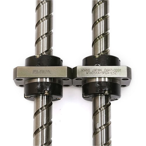
Bearing Types Used in Each Configuration
Fixed End Bearings
The fixed end must resist both radial and thrust loads in both directions. The standard solution is duplex angular contact ball bearings mounted face-to-face (DF) or back-to-back (DB).
- DF (Face-to-Face) mounting: Good for misalignment tolerance, lower moment rigidity
- DB (Back-to-Back) mounting: Higher moment rigidity, better for high-speed operation
- Triplex sets (two + one): Used for very high axial loads, common on large clamping axes
Angular contact bearings are typically preloaded at the factory to eliminate internal clearance and maximize rigidity. Common preload classes are light, medium, and heavy — matched to the application load requirements.
Supported End Bearings
The supported end only needs radial location; axial float is required. Deep groove ball bearings are the standard choice. They handle radial loads well and allow the screw shaft to slide axially through the bearing inner ring as it thermally expands.
Some supported-end bearings use a cylindrical roller bearing design for higher radial load capacity, but deep groove ball bearings are by far the most common in injection molding machines.
Critical Speed: Why Configuration Matters
Critical speed is the RPM at which the screw begins to resonate laterally (whirl). Operating at or near critical speed causes severe vibration, noise, and accelerated wear.
The formula for critical speed depends heavily on the support configuration:
表格
| Configuration | Critical Speed Factor | Relative to Fixed-Free |
|---|---|---|
| Fixed-Free | 1.0× | Baseline |
| Supported-Supported | 3.7× | 3.7× higher |
| Fixed-Supported | 4.5× | 4.5× higher |
| Fixed-Fixed | 6.0× | 6.0× higher |
For a 40 mm diameter, 1,500 mm long screw:
- Fixed-free → ~800 RPM (too slow for injection)
- Fixed-supported → ~3,600 RPM (suitable for most injection axes)
- Fixed-fixed → ~4,800 RPM (high-speed packaging machines)
This is why fixed-supported is the minimum acceptable configuration for injection axes — anything lower simply can't reach the required speeds without dangerous vibration.
Thermal Growth & Bearing Design
Thermal expansion is a major consideration in bearing configuration selection.
Fixed-Supported Thermal Behavior:
The screw grows toward the supported end, which has a floating bearing. No additional stress is created. This is thermally stable and forgiving.
Fixed-Fixed Thermal Behavior:
Both ends are constrained, so thermal expansion creates compressive axial force in the screw. This force adds to the bearing preload and can:
- Overload bearings, shortening life
- Cause the screw to bow slightly, reducing accuracy
- Increase friction and heat generation
Solutions for fixed-fixed thermal issues:
- Cooled screws — hollow shaft with circulating coolant maintains constant temperature
- Precision preload calculation — set initial bearing preload low enough that thermal growth doesn't exceed safe limits
- One semi-fixed end — a compromise where one end has limited axial float via spring-loaded bearings
Practical Installation Tips
-
Alignment is critical Misalignment between the screw axis and bearing bores creates binding, excessive friction, and premature bearing failure. Use precision alignment tools during installation.
-
Bearing preload must be correct Under-preloaded bearings have internal clearance → backlash and reduced rigidity. Over-preloaded bearings run hot and wear fast. Always follow manufacturer torque specifications.
-
Lock nuts must be properly secured The shaft lock nut that sets bearing preload must be locked with a set screw or locking plate. Vibration from machine operation can loosen improperly secured lock nuts, causing catastrophic preload loss.
-
Seal properly against contamination Injection molding shops have plastic dust, oil mist, and cooling water. Bearing seals must be rated for the environment. Consider adding external labyrinth seals or covers for extra protection.
-
Lubricate correctly Support bearings need proper grease — not too much (churning causes heat) and not too little (metal contact causes wear). Follow the manufacturer's recommended grease quantity and relubrication interval.
Conclusion
Ball screw support bearing configuration is a foundational engineering decision that affects rigidity, speed capability, thermal behavior, and service life of every axis on an all-electric injection molding machine.
Quick reference for injection molding:
- Clamping axis: Fixed-supported (standard) or fixed-fixed (high-precision / large tonnage)
- Injection axis: Fixed-supported (universal standard)
- Ejector axis: Fixed-supported
- Nozzle touch: Supported-supported (economy) or fixed-supported (precision)
Understanding the trade-offs between rigidity, critical speed, thermal management, and cost allows machine builders and maintenance teams to make the right choice for each application. And for molders troubleshooting vibration or accuracy issues, checking the support bearing condition and configuration should be one of the first diagnostic steps.