 EN
EN
 AR
AR
 BG
BG
 CS
CS
 DA
DA
 NL
NL
 FI
FI
 FR
FR
 DE
DE
 EL
EL
 HI
HI
 IT
IT
 JA
JA
 KO
KO
 NO
NO
 PL
PL
 PT
PT
 RU
RU
 ES
ES
 SV
SV
 TL
TL
 ID
ID
 UK
UK
 VI
VI
 HU
HU
 TH
TH
 TR
TR
 FA
FA
 AF
AF
 MS
MS
 SW
SW
 GA
GA
 CY
CY
 BE
BE
 KA
KA
 LA
LA
 MY
MY
 TG
TG
 UZ
UZ


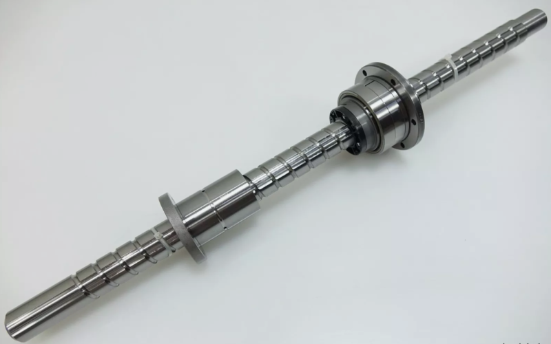
When specifying ball screws for all-electric injection molding machines, one of the most consequential decisions is also one of the most frequently overlooked: screw lead. The lead — the distance the nut travels per single revolution of the screw shaft — directly determines the relationship between motor speed, linear speed, and thrust force.
Choose too fine a lead, and the machine can't reach required injection speeds. Choose too coarse a lead, and you lose thrust force and positioning resolution. Getting it right means the machine hits every performance target; getting it wrong means compromised speed, force, or accuracy.
This guide explains how ball screw lead works, the trade-offs involved, and how to select the optimal lead for each axis of an injection molding machine.
What Is Ball Screw Lead?
The lead of a ball screw is the linear distance the nut advances with one full 360° rotation of the screw shaft. It is measured in millimeters per revolution (mm/rev).
Common lead sizes for injection molding applications include:
- Fine leads: 5 mm, 6 mm, 8 mm, 10 mm/rev
- Medium leads: 16 mm, 20 mm, 25 mm/rev
- High leads: 32 mm, 40 mm, 50 mm/rev
- Ultra-high leads: 63 mm, 80 mm, 100 mm/rev
Important: Lead ≠ pitch Pitch is the distance between adjacent thread crests. For single-start screws, lead equals pitch. For multi-start screws (2-start, 4-start, etc.), lead = pitch × number of starts. High-lead ball screws are almost always multi-start designs to maintain proper ball size and load capacity.
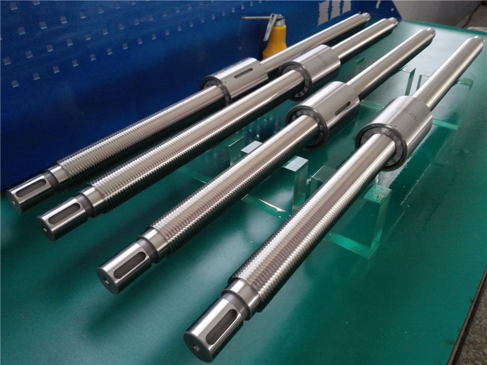
The Fundamental Trade-Off: Speed vs Thrust
Ball screw lead creates an inverse relationship between linear speed and thrust force, governed by basic mechanical principles:
Linear speed = Screw RPM × Lead
- Doubling the lead doubles the linear speed at the same RPM
- Example: 1,500 RPM × 10 mm lead = 15 m/min; 1,500 RPM × 20 mm lead = 30 m/min
Thrust force = Torque × 2π / Lead × Efficiency
- Doubling the lead halves the thrust force at the same torque
- Example: 10 Nm torque × 2π / 0.01 m × 90% eff = ~5,650 N; with 20 mm lead → ~2,825 N
This is the core trade-off:
- Fine lead → high thrust, low speed, high positioning resolution
- High lead → low thrust, high speed, lower positioning resolution
The job of the design engineer is to find the lead that satisfies both the speed requirement AND the thrust requirement, given the available motor torque.
Lead Selection by Injection Molding Axis
Each axis of an injection molding machine has different speed and force requirements, so each needs a different lead strategy.
1. Clamping Axis
Recommended: Fine to Medium Lead (10–20 mm/rev)
The clamping axis requires maximum thrust force and moderate speed. Mold closing force can range from 50 kN on small machines to over 5,000 kN on large tonnage machines.
Why fine-to-medium lead:
- High mechanical advantage generates enormous clamping force from reasonable motor torque
- Speed is acceptable — clamping strokes are relatively slow operations
- Fine resolution allows precise mold protection (low-pressure close) positioning
Typical examples:
- Small machine (50–100T): 16 mm lead, Ø40 mm screw
- Medium machine (200–350T): 20 mm lead, Ø50–63 mm screw
- Large machine (500T+): 16–20 mm lead, Ø80–100 mm screw (often dual-screw design)
Key consideration: Clamping axes typically use the largest diameter screws with the finest leads relative to shaft size, maximizing thrust capacity.
2. Injection Axis
Recommended: Medium to High Lead (20–40 mm/rev)
The injection axis needs both high speed (for fast fill of thin-wall parts) and significant force (for packing and holding pressure). This is the most challenging axis for lead selection because it pushes both ends of the speed/force spectrum.
Why medium-to-high lead:
- Must achieve injection speeds of 100–300 mm/s for thin-wall and packaging applications
- Must also generate 50–200 kN of injection force for packing
- Medium leads provide the best balance between the two requirements
Typical examples:
- General purpose (100–200T): 20–25 mm lead, Ø40–50 mm screw
- High-speed packaging: 32–40 mm lead, Ø50–63 mm screw
- Precision / optical: 16–20 mm lead, Ø32–40 mm screw (prioritizes resolution over speed)
Key consideration: For high-speed injection, the lead is often the limiting factor on maximum injection speed. If the required speed exceeds what a standard lead can deliver at the motor's maximum RPM, a higher lead screw is needed — but only if the motor has enough torque to maintain injection force at that lead.
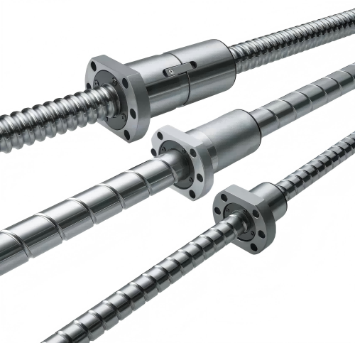
3. Ejector Axis
Recommended: Medium Lead (10–20 mm/rev)
Ejection requires moderate speed and relatively low force compared to clamping or injection.
Why medium lead:
- Ejection forces are typically 5–20% of clamping force
- Speed is important for cycle time, but not as critical as injection speed
- Fine enough resolution for precise ejector pin positioning
Typical examples:
- Small machine: 10 mm lead, Ø20–25 mm screw
- Medium machine: 16 mm lead, Ø32–40 mm screw
- Large machine: 20 mm lead, Ø40–50 mm screw
4. Injection Unit Traverse / Nozzle Touch
Recommended: Medium to High Lead (20–32 mm/rev)
Nozzle touch is a low-force, moderate-speed axis. Higher leads work well here because force requirements are minimal.
Why higher lead:
- Low force requirement means mechanical advantage is not critical
- Faster traverse reduces cycle time
- Coarser resolution is acceptable for nozzle contact
How to Calculate the Right Lead
The lead selection process involves checking both speed and force requirements against the available motor.
Step 1: Determine required linear speed Calculate the maximum linear speed the axis must achieve:
- Injection axis: injection speed (mm/s) × 60 = mm/min
- Clamping axis: mold close speed (mm/s) × 60 = mm/min
Step 2: Calculate required screw RPM RPM = Required linear speed (mm/min) ÷ Lead (mm/rev)
Check that this RPM is within the motor's rated speed AND the screw's critical speed and DN rating.
Step 3: Calculate required motor torque Torque (Nm) = Thrust force (N) × Lead (m/rev) ÷ (2π × Efficiency)
Where efficiency is typically 0.85–0.95 for ball screws.
Check that this torque is within the motor's continuous and peak torque ratings.
Step 4: Verify positioning resolution Minimum incremental movement = Lead ÷ (Motor encoder resolution × Gear ratio)
Ensure this is finer than the required positioning accuracy for the application.
Multi-Start Screws: High Lead Without Sacrificing Load Capacity
A common misconception is that high-lead screws have lower load capacity. This is not necessarily true, thanks to multi-start screw design.
Single-start vs multi-start:
- Single-start: One continuous thread. Lead = pitch.
- 2-start: Two parallel threads. Lead = 2 × pitch.
- 4-start: Four parallel threads. Lead = 4 × pitch.
Multi-start screws achieve high lead while maintaining a reasonable pitch (distance between adjacent threads). This means:
- Ball size stays the same → load capacity stays the same
- Nut size stays the same → interchangeability is maintained
- Only the lead changes → speed capability increases
For example, a Ø40 mm screw is available in:
- 40-5 (single-start, 5 mm lead) — high thrust, low speed
- 40-10 (2-start, 10 mm lead) — medium thrust, medium speed
- 40-20 (4-start, 20 mm lead) — lower thrust, high speed
All use the same ball size and have similar dynamic load ratings, but the 20 mm lead version delivers 4× the linear speed at the same RPM.
DN Value: The Hidden Constraint
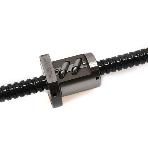
When selecting lead for high-speed applications, you must also check the DN value — the product of screw diameter (D, mm) and rotational speed (N, RPM). DN is a measure of how fast the balls are traveling inside the nut, and it has a maximum limit determined by the screw's design and lubrication.
DN Value: The Hidden Constraint
When selecting lead for high-speed applications, you must also check the DN value — the product of screw diameter (D, mm) and rotational speed (N, RPM). DN is a measure of how fast the balls are traveling inside the nut, and it has a maximum limit determined by the screw's design and lubrication.
Typical DN limits:
- Standard precision ground screws: ~70,000–100,000 DN
- High-speed optimized screws: ~120,000–160,000 DN
- Ultra-high-speed special designs: up to 220,000 DN
Why this matters for lead selection: If you need 30 m/min of linear speed with a 10 mm lead, that's 3,000 RPM. For a Ø40 mm screw, DN = 40 × 3,000 = 120,000 — which may exceed the screw's rating.
With a 20 mm lead, you only need 1,500 RPM for the same 30 m/min. DN = 40 × 1,500 = 60,000 — well within limits.
Key insight: Higher lead screws run at lower RPM for the same linear speed, which reduces DN value and extends service life. This is a major reason high-lead screws are preferred for high-speed injection applications.
Common Lead Selection Mistakes
Mistake 1: Choosing lead based on speed only Many engineers size the lead to hit the target speed but forget to verify thrust force. The result is a machine that moves fast but can't generate enough injection pressure or clamping force. Always check both speed AND force.
Mistake 2: Over-sizing the lead "just to be safe" A higher lead than necessary means:
- Lower mechanical advantage → larger, more expensive motor needed
- Coarser positioning resolution → may not meet precision requirements
- Higher inertial reflected to the motor → tuning challenges
Mistake 3: Ignoring critical speed Long screws with high leads may operate above critical speed at maximum RPM, causing dangerous vibration. Always calculate critical speed for the selected diameter, length, and support configuration.
Mistake 4: Forgetting about acceleration Injection molding axes accelerate and decelerate rapidly. The torque required for acceleration adds to the torque required for thrust force. If the lead is too fine, the motor may not have enough torque for fast acceleration, even if steady-state force is fine.
Lead Selection Quick Reference Table
表格
| Axis | Typical Lead Range | Screw Diameter Range | Priority |
|---|---|---|---|
| Clamping | 10–20 mm/rev | Ø40–100 mm | Thrust force > speed |
| Injection (general) | 20–25 mm/rev | Ø32–50 mm | Balanced speed & force |
| Injection (high-speed) | 32–40 mm/rev | Ø40–63 mm | Speed > force |
| Injection (precision) | 16–20 mm/rev | Ø32–40 mm | Resolution > speed |
| Ejector | 10–20 mm/rev | Ø20–50 mm | Balanced |
| Nozzle touch | 20–32 mm/rev | Ø20–32 mm | Speed > force |
Conclusion
Ball screw lead is a fundamental parameter that shapes the performance character of every axis on an all-electric injection molding machine. It is the lever that trades speed for force — and finding the right balance is essential.
Key takeaways:
- Clamping axes: Fine leads for maximum thrust
- Injection axes: Medium leads for balanced speed and force; high leads for thin-wall / high-speed machines
- Ejector axes: Medium leads for moderate speed and force
- Multi-start design achieves high lead without sacrificing load capacity
- DN value often favors higher leads for high-speed applications (lower RPM = lower DN)
By carefully matching lead to each axis's specific speed, force, and precision requirements, machine builders and retrofitting engineers can optimize performance, minimize motor size and cost, and maximize the service life of the ball screw assembly.