 EN
EN
 AR
AR
 BG
BG
 CS
CS
 DA
DA
 NL
NL
 FI
FI
 FR
FR
 DE
DE
 EL
EL
 HI
HI
 IT
IT
 JA
JA
 KO
KO
 NO
NO
 PL
PL
 PT
PT
 RU
RU
 ES
ES
 SV
SV
 TL
TL
 ID
ID
 UK
UK
 VI
VI
 HU
HU
 TH
TH
 TR
TR
 FA
FA
 AF
AF
 MS
MS
 SW
SW
 GA
GA
 CY
CY
 BE
BE
 KA
KA
 LA
LA
 MY
MY
 TG
TG
 UZ
UZ

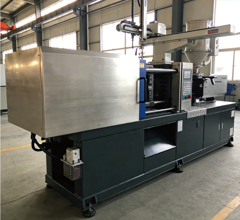
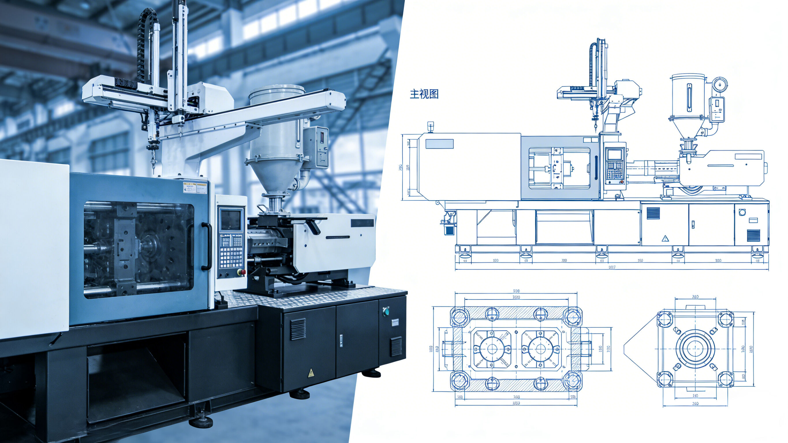
Injection molding machines are precision equipment integrating mechanical, hydraulic, electrical, and automation technologies, where ball screws and linear guides play a crucial role as core transmission and guidance components. They are widely used in key functional systems such as the injection system, clamping system, and mold adjustment mechanism, ensuring the high precision, stability, and efficiency of the equipment during the molding process. This document focuses on the application principles, installation positions, functional advantages, and matching design of ball screws and linear guides in injection molding machines, combined with drawing instructions (including detailed dimension marking, model parameters, and installation requirements) for clear understanding.
1. Overview of Ball Screws and Linear Guides
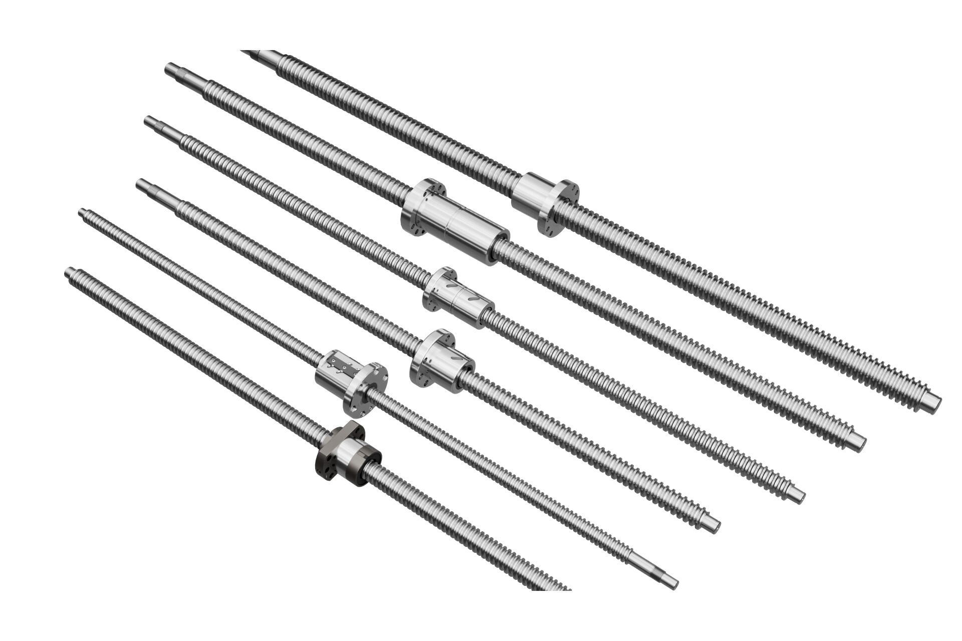
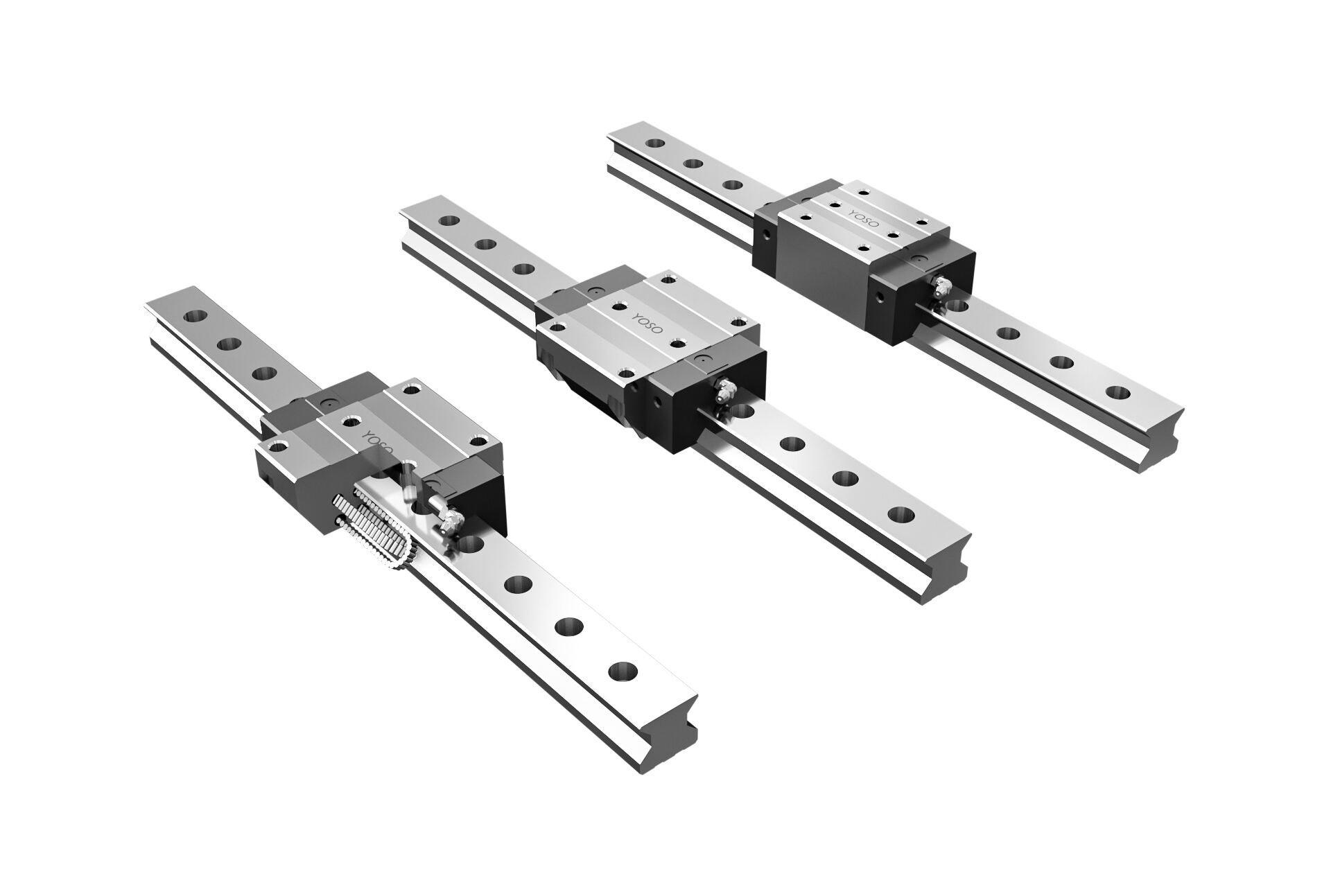
Ball screws are high-precision transmission components that convert rotational motion into linear motion (or vice versa) with high efficiency, low friction, and high positioning accuracy. They consist of a screw shaft, nut, balls, and a return mechanism, and are widely used in scenarios requiring precise linear movement and load-bearing in injection molding machines. Linear guides, as key guidance components, provide stable and smooth linear guidance for moving parts, resist lateral loads and moments, and ensure the positional accuracy of moving components during long-term operation. Together, ball screws and linear guides form a high-precision transmission-guidance system, which is the core guarantee for the stable operation of injection molding machines. The model selection and dimension parameters of ball screws and linear guides are closely related to the tonnage of the injection molding machine and the working conditions of each system, which will be detailed in the following application scenarios.
2. Application of Ball Screws in Injection Molding Machines
Ball screws are mainly used in the injection system, mold adjustment mechanism, and ejection system of injection molding machines, where precise linear motion and load transmission are required. The specific application scenarios, matching drawings (with detailed marking), model parameters, installation dimensions, and functional advantages are as follows:
2.1 Application in the Injection System
The injection system is the core of the injection molding machine, and the ball screw is mainly used in the injection seat movement mechanism and the screw axial movement control, which directly affects the injection precision and speed stability. This application is suitable for injection molding machines with a clamping force of 50-500 tons, and the model and installation dimensions of the ball screw are determined according to the stroke of the injection seat and the injection force.
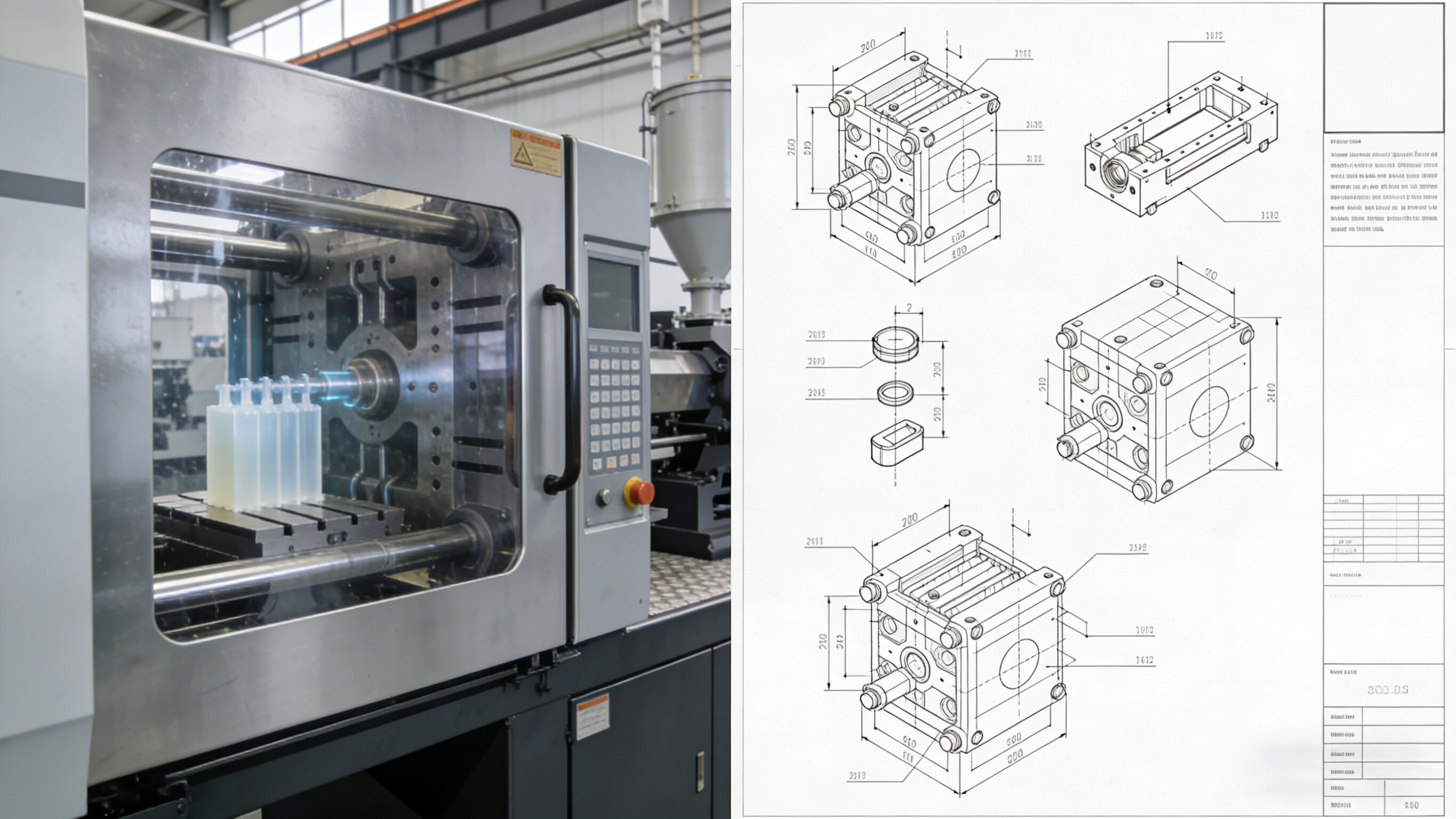
Matching Drawing Description (Detailed Marking): As shown in Drawing 1 (Injection System Transmission Structure), the ball screw is horizontally installed at the bottom of the injection seat, parallel to the axis of the barrel. The drawing clearly marks the key dimensions: the total length of the ball screw is 800-1200mm (depending on the injection seat stroke), the diameter of the screw shaft is Φ32-Φ50mm, the lead is 10-20mm, and the installation center distance between the ball screw and the barrel axis is 120-180mm. One end of the ball screw is connected to a servo motor (model: 1.5-3kW) through a coupling (model: KTR-BOWEX), and the nut is fixed on the injection seat with M8-M12 hexagon socket head cap screws (installation hole spacing: 60-80mm). When the servo motor rotates, the ball screw converts rotational motion into linear motion, driving the injection seat to move forward (injection direction) or backward (retraction direction) along the linear guide. The drawing also marks the parallelism tolerance between the ball screw and the linear guide (≤0.02mm/m) to ensure movement accuracy.
Recommended Model & Installation Parameters: ① Ball screw model: SFU3210-SFU5020 (C3-C5 precision grade, suitable for medium and small tonnage injection molding machines); ② Installation dimensions: Screw shaft diameter Φ32-Φ50mm, lead 10-20mm, total length 800-1200mm, nut installation hole spacing 60-80mm; ③ Installation requirement: The parallelism between the ball screw and the barrel axis is ≤0.02mm/m, and the verticality between the ball screw and the injection seat bottom plate is ≤0.03mm/m.
Functional Advantages: ① High positioning accuracy: The positioning error of the ball screw is within ±0.01mm, which ensures that the injection seat can be accurately aligned with the mold gate, avoiding deviation and affecting the injection effect; ② High transmission efficiency: The transmission efficiency of the ball screw is up to 90%-98%, which is much higher than that of ordinary lead screws, reducing the energy consumption of the servo motor and improving the response speed of the injection seat; ③ Stable load-bearing capacity: It can bear the axial load (5-20kN) generated during injection, ensuring that the injection seat does not shift during the high-pressure injection process, and maintaining the stability of the injection pressure.
2.2 Application in the Mold Adjustment Mechanism
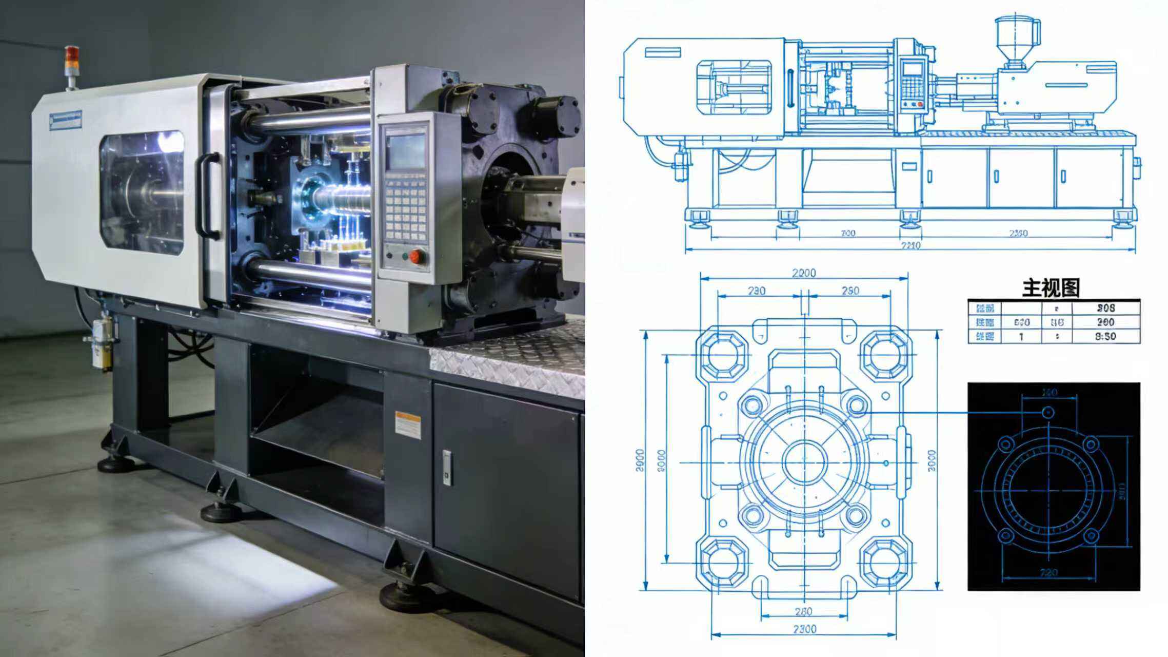
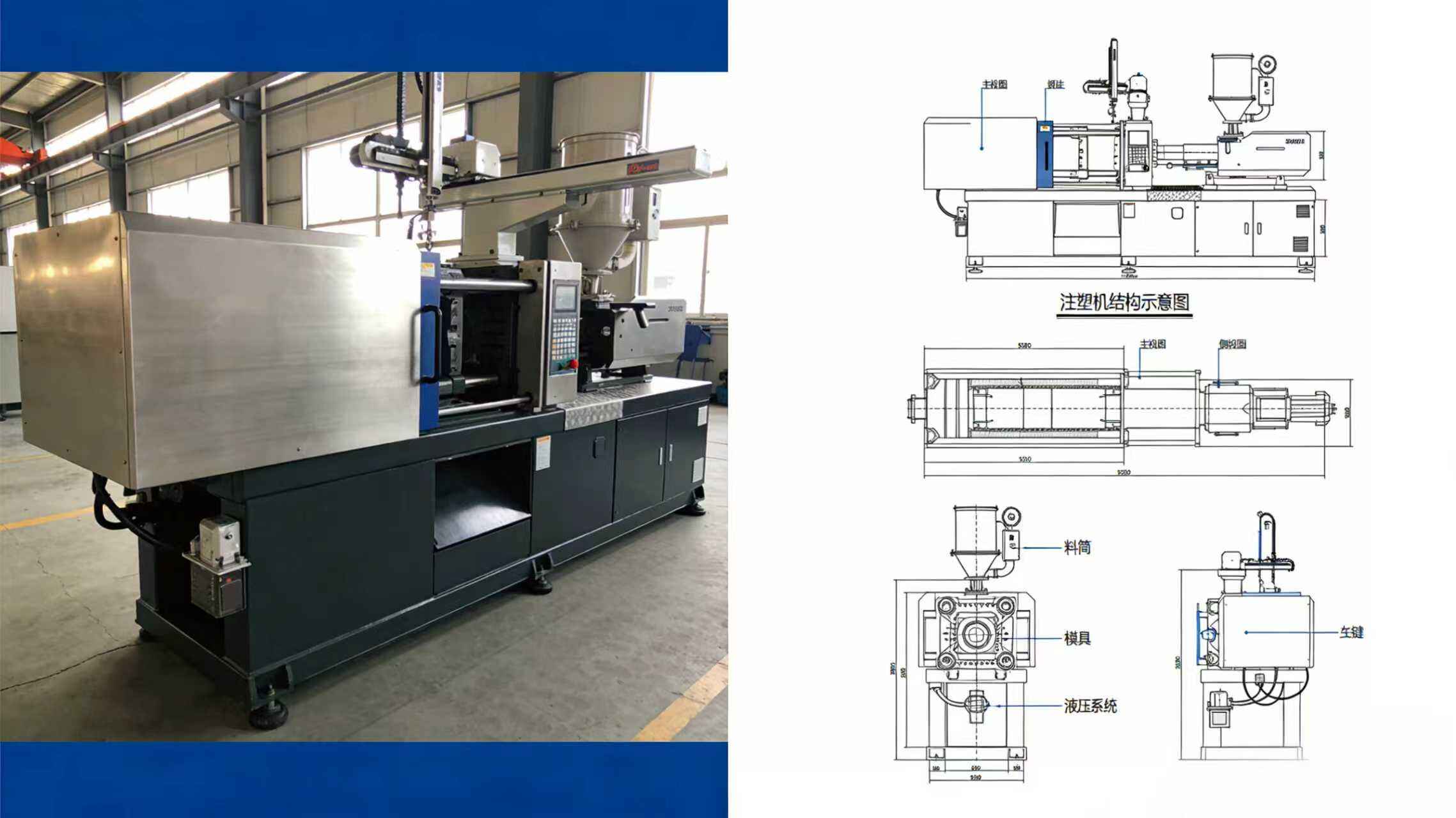
The mold adjustment mechanism is used to adjust the distance between the fixed mold and the moving mold to adapt to molds of different thicknesses, and the ball screw is the core component to realize precise mold adjustment. This application is suitable for injection molding machines with a clamping force of 100-1000 tons, and four ball screws are symmetrically installed to ensure synchronous movement of the moving mold plate.
Matching Drawing Description (Detailed Marking): As shown in Drawing 2 (Mold Adjustment Mechanism Structure), four ball screws are symmetrically installed at the four corners of the clamping system (installation hole position: 400-800mm from the center of the mold plate, depending on the machine tonnage), connected to a synchronous transmission mechanism (gear box model: SEW-R17/R27 or timing belt model: HTD5M-1500). The drawing marks the key parameters: the ball screw diameter is Φ40-Φ80mm, the lead is 16-32mm, the total length is 1000-2000mm, and the distance between the four ball screws is consistent with the size of the moving mold plate (600-1200mm in length and width). The nut of the ball screw is connected to the moving mold plate with M12-M16 hexagon socket head cap screws (installation hole spacing: 80-120mm), and the screw shaft is fixed on the fixed mold plate with a bearing seat (model: SKF 6208-6214). When the mold adjustment motor rotates, the four ball screws rotate synchronously, driving the moving mold plate to move linearly along the linear guide, realizing the adjustment of the mold opening and closing distance (adjustment stroke: 200-500mm). The drawing also marks the synchronous error of the four ball screws (≤0.03mm) to avoid mold tilting.
Recommended Model & Installation Parameters: ① Ball screw model: SFU4016-SFU8032 (C3-C4 precision grade, high rigidity and load-bearing capacity); ② Installation dimensions: Screw shaft diameter Φ40-Φ80mm, lead 16-32mm, total length 1000-2000mm, four screws symmetrically installed (hole spacing 600-1200mm); ③ Installation requirement: The synchronous error of the four ball screws is ≤0.03mm, and the perpendicularity between the screw shaft and the mold plate is ≤0.02mm/m.
Functional Advantages: ① Synchronous precision: The four ball screws are driven synchronously, ensuring that the moving mold plate moves stably and horizontally without tilting, avoiding mold damage caused by uneven force; ② Precise adjustment: The mold adjustment accuracy can reach ±0.02mm, which is suitable for precision molds and ensures the fitting accuracy of the mold; ③ Self-locking performance: The ball screw with a certain lead (lead ≤20mm) has good self-locking performance, which can prevent the moving mold plate from sliding under the action of external force after mold adjustment, ensuring the safety of the molding process.
2.3 Application in the Ejection System
The ejection system is used to push the formed plastic products out of the mold, and the ball screw is used to drive the ejection rod to move linearly, ensuring the stability and uniformity of the ejection action. This application is suitable for all tonnages of injection molding machines, and the model of the ball screw is determined according to the ejection stroke and ejection force.
Matching Drawing Description (Detailed Marking): As shown in Drawing 3 (Ejection System Structure), the ball screw is vertically installed at the bottom of the moving mold plate (installation center position: aligned with the center of the ejection plate), and the drawing marks the key dimensions: the ball screw diameter is Φ25-Φ40mm, the lead is 8-16mm, the total length is 300-600mm, and the distance between the ball screw and the ejection rod is 50-80mm. The nut of the ball screw is connected to the ejection plate with M6-M10 hexagon socket head cap screws (installation hole spacing: 40-60mm), and the top of the screw shaft is equipped with a limit switch (model: Omron ZC-Q2155) to control the ejection stroke (adjustable range: 50-200mm). The servo motor (model: 0.75-1.5kW) drives the ball screw to rotate, converting rotational motion into linear motion, and the ejection plate drives the ejection rod to move upward, pushing the product out of the mold. After ejection, the ball screw reverses to drive the ejection plate to reset. The drawing also marks the verticality between the ball screw and the ejection plate (≤0.02mm/m) to ensure the stability of the ejection action.
Recommended Model & Installation Parameters: ① Ball screw model: SFU2508-SFU4016 (C4-C5 precision grade, small volume and high precision); ② Installation dimensions: Screw shaft diameter Φ25-Φ40mm, lead 8-16mm, total length 300-600mm, installation center aligned with the ejection plate center; ③ Installation requirement: The verticality between the ball screw and the ejection plate is ≤0.02mm/m, and the ejection stroke limit error is ≤0.01mm.
Functional Advantages: ① Stable ejection speed: The ball screw can realize stepless speed regulation, ensuring that the ejection speed is uniform and stable, avoiding product deformation or damage caused by sudden acceleration or deceleration; ② Accurate stroke control: The stroke of the ejection rod can be precisely controlled through the ball screw, adapting to products of different heights and ensuring complete ejection of the product; ③ Low wear: The ball screw has low friction and wear, which can ensure the service life of the ejection system and reduce maintenance costs.
3. Application of Linear Guides in Injection Molding Machines
Linear guides are mainly used to provide linear guidance for moving components such as the injection seat, moving mold plate, and ejection plate, ensuring that the moving parts move smoothly and accurately without deviation. They are usually used in conjunction with ball screws to form a complete transmission-guidance system, and their model and installation dimensions are matched with the corresponding ball screws. The specific application scenarios, matching drawings (with detailed marking), model parameters, installation dimensions, and functional advantages are as follows:
3.1 Application in the Injection Seat
The injection seat needs to move linearly back and forth during the injection process, and the linear guide provides stable guidance for it, ensuring that the injection seat moves along the fixed direction without lateral deviation. It is used with the ball screw in the injection system, and the model is selected according to the load of the injection seat.
Matching Drawing Description (Detailed Marking): As shown in Drawing 1 (Injection System Transmission Structure), two linear guides are symmetrically installed on both sides of the ball screw, parallel to the ball screw (parallelism tolerance ≤0.02mm/m). The drawing marks the key parameters: the linear guide model is HGH25-HGH35, the guide rail length is 800-1200mm (consistent with the ball screw length), the cross-section width of the guide rail is 25-35mm, and the installation center distance between the two linear guides is 150-220mm. The slider of the linear guide is fixed on the bottom of the injection seat with M6-M8 hexagon socket head cap screws (installation hole spacing: 50-70mm), and the guide rail is fixed on the machine base with M8-M10 expansion screws (installation hole spacing: 100-150mm). When the ball screw drives the injection seat to move, the slider slides along the guide rail, ensuring the stability and accuracy of the injection seat's movement. The drawing also marks the lateral clearance of the slider (≤0.01mm) to ensure guidance precision.
Recommended Model & Installation Parameters: ① Linear guide model: HGH25CA-HGH35CA (square slider, high load-bearing capacity); ② Installation dimensions: Guide rail length 800-1200mm, cross-section width 25-35mm, two guides symmetrically installed (center distance 150-220mm); ③ Installation requirement: Parallelism between the linear guide and the ball screw is ≤0.02mm/m, lateral clearance of the slider ≤0.01mm.
Functional Advantages: ① High guidance accuracy: The linear guide has small lateral clearance, which can effectively prevent the injection seat from shaking during movement, ensuring that the barrel and the mold gate are accurately aligned; ② High load-bearing capacity: It can bear the lateral load (2-8kN) generated during the injection process, avoiding the deformation of the injection seat and ensuring the stability of the injection system; ③ Smooth movement: The rolling friction between the slider and the guide rail is small, which ensures that the injection seat moves smoothly, reducing the noise and energy consumption of the equipment.
3.2 Application in the Clamping System
The moving mold plate in the clamping system needs to move linearly to realize mold opening and closing, and the linear guide is the key component to ensure the smooth movement of the moving mold plate. It is used with the four ball screws in the mold adjustment mechanism, and the number of linear guides is 2-4 according to the tonnage of the injection molding machine.
Matching Drawing Description (Detailed Marking): As shown in Drawing 2 (Mold Adjustment Mechanism Structure), two or four linear guides are installed on the machine base, parallel to the ball screws (parallelism tolerance ≤0.02mm/m). For injection molding machines with a clamping force of 100-500 tons, two linear guides are used; for 500-1000 tons, four linear guides are used. The drawing marks the key parameters: the linear guide model is HGH45-HGH65, the guide rail length is 1000-2000mm (consistent with the ball screw length), the cross-section width of the guide rail is 45-65mm, and the installation center distance between the guide rails is 300-600mm. The slider of the linear guide is fixed on the bottom of the moving mold plate with M10-M12 hexagon socket head cap screws (installation hole spacing: 80-100mm), and the guide rail is fixed on the machine base with M12-M16 expansion screws (installation hole spacing: 150-200mm). When the ball screws drive the moving mold plate to move, the slider slides along the guide rail, ensuring that the moving mold plate moves horizontally and stably. The drawing also marks the verticality between the guide rail and the mold plate (≤0.02mm/m) to avoid mold deviation.
3.3 Application in the Ejection System
Recommended Model & Installation Parameters: ① Linear guide model: HGH45CA-HGH65CA (heavy-duty type, high rigidity); ② Installation dimensions: Guide rail length 1000-2000mm, cross-section width 45-65mm, 2-4 guides installed (center distance 300-600mm); ③ Installation requirement: Parallelism between the linear guide and the ball screw is ≤0.02mm/m, verticality between the guide rail and the mold plate is ≤0.02mm/m.
Functional Advantages: ① Uniform force: The linear guide distributes the load evenly on the moving mold plate, avoiding local stress concentration and preventing the moving mold plate from deformation; ② High rigidity: The linear guide has high rigidity, which can withstand the clamping force (100-1000kN) generated during mold closing, ensuring the stability of the mold during the molding process; ③ Long service life: The linear guide is made of high-hardness materials (SUJ2) and undergoes surface quenching treatment (HRC60-62), which has good wear resistance and corrosion resistance, and can adapt to the harsh working environment of injection molding machines.
3.3 Application in the Ejection System
The ejection plate in the ejection system needs to move linearly up and down, and the linear guide provides guidance for it, ensuring the stability and accuracy of the ejection action. It is used with the ball screw in the ejection system, and two linear guides are symmetrically installed to ensure the stability of the ejection plate.
Matching Drawing Description (Detailed Marking): As shown in Drawing 3 (Ejection System Structure), two linear guides are vertically installed on both sides of the ball screw (parallelism tolerance ≤0.02mm/m). The drawing marks the key parameters: the linear guide model is HGW20-HGW25, the guide rail length is 300-600mm (consistent with the ball screw length), the cross-section width of the guide rail is 20-25mm, and the installation center distance between the two linear guides is 80-120mm. The slider of the linear guide is fixed on the ejection plate with M5-M6 hexagon socket head cap screws (installation hole spacing: 30-50mm), and the guide rail is fixed on the moving mold plate with M6-M8 hexagon socket head cap screws (installation hole spacing: 80-100mm). When the ball screw drives the ejection plate to move up and down, the slider slides along the guide rail, ensuring that the ejection plate moves stably without deviation. The drawing also marks the verticality between the linear guide and the ball screw (≤0.02mm/m) to ensure the accuracy of the ejection rod.
Recommended Model & Installation Parameters: ① Linear guide model: HGW20CC-HGW25CC (flange slider, easy installation); ② Installation dimensions: Guide rail length 300-600mm, cross-section width 20-25mm, two guides symmetrically installed (center distance 80-120mm); ③ Installation requirement: Parallelism between the linear guide and the ball screw is ≤0.02mm/m, verticality between the guide rail and the ejection plate is ≤0.02mm/m.
Functional Advantages: ① Accurate guidance: The linear guide ensures that the ejection plate moves along the vertical direction, avoiding the inclination of the ejection rod and ensuring that the product is evenly stressed during ejection; ② Stable operation: The rolling friction of the linear guide is small, which reduces the resistance during the movement of the ejection plate, ensuring the stability of the ejection speed and the quality of the product; ③ Easy maintenance: The linear guide has a simple structure and is easy to lubricate and maintain, which can reduce the maintenance workload of the equipment.
4. Key Matching Design of Ball Screws and Linear Guides in Injection Molding Machines
The matching design of ball screws and linear guides directly affects the performance of the injection molding machine. The following key points need to be paid attention to, combined with the model parameters and installation dimensions mentioned above:
-
Model Selection: According to the load, speed, and positioning accuracy requirements of different systems of the injection molding machine, select the appropriate model of ball screws and linear guides. For example, the injection system requires high positioning accuracy, so ball screws with high precision (C3-C5 grade) and linear guides with small clearance should be selected; the clamping system bears large load, so ball screws (SFU4016-SFU8032) and linear guides (HGH45-HGH65) with high load-bearing capacity should be selected; the ejection system has small load and short stroke, so small-sized ball screws (SFU2508-SFU4016) and linear guides (HGW20-HGW25) can be selected.
-
Installation Accuracy: During installation, ensure that the ball screw and linear guide are parallel to each other (parallelism tolerance ≤0.02mm/m), and the installation surface is flat and smooth (flatness ≤0.01mm/m), avoiding installation deviation, which will affect the transmission and guidance accuracy. At the same time, ensure that the connection between the ball screw, linear guide and other components is firm, and there is no looseness; the tightening torque of the fixing screws should be controlled according to the screw size (M6: 5-8N·m, M8: 10-15N·m, M10: 15-20N·m).
-
Lubrication and Maintenance: Regularly lubricate the ball screws and linear guides with appropriate lubricating oil or grease (recommended: lithium-based grease, viscosity grade ISO VG220) to reduce friction and wear, and extend their service life. The lubrication cycle is once every 8 hours for continuous operation; at the same time, regularly clean the guide rails and ball screws to avoid the accumulation of plastic debris and other impurities, which will affect the operation of the components.
-
Drawing Coordination: In the design drawing of the injection molding machine, the installation position, size, and connection mode of the ball screws and linear guides should be clearly marked, including the model, diameter, lead, length of the ball screw, the model, length, cross-section size of the linear guide, the installation hole spacing, and the parallelism/verticality tolerance. The matching relationship with other components (such as servo motors, coupling, bearing seats, and moving parts) should be accurately reflected to ensure the rationality and feasibility of the overall structure.
5. Summary
Ball screws and linear guides are core components in injection molding machines, which are widely used in the injection system, clamping system, and ejection system. They work together to realize precise transmission and stable guidance, ensuring the high precision, efficiency, and stability of the injection molding machine during the molding process. The reasonable selection of models (matched with the tonnage and working conditions of the injection molding machine), correct installation (strictly controlling the parallelism, verticality, and tightening torque), and regular maintenance of ball screws and linear guides can not only improve the performance of the injection molding machine but also extend the service life of the equipment, reduce maintenance costs, and provide a strong guarantee for the production of high-quality plastic products. The matching drawings of each application scenario clearly show the installation position, model parameters, and dimension marks of the components, which is convenient for the design, installation, and maintenance of the injection molding machine.