 EN
EN
 AR
AR
 BG
BG
 CS
CS
 DA
DA
 NL
NL
 FI
FI
 FR
FR
 DE
DE
 EL
EL
 HI
HI
 IT
IT
 JA
JA
 KO
KO
 NO
NO
 PL
PL
 PT
PT
 RU
RU
 ES
ES
 SV
SV
 TL
TL
 ID
ID
 UK
UK
 VI
VI
 HU
HU
 TH
TH
 TR
TR
 FA
FA
 AF
AF
 MS
MS
 SW
SW
 GA
GA
 CY
CY
 BE
BE
 KA
KA
 LA
LA
 MY
MY
 TG
TG
 UZ
UZ

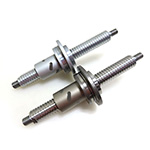
When selecting linear drive equipment, the ball screw shaft diameter (outer diameter) and lead are the core parameters that determine the load, operating speed, positioning accuracy, and equipment lifespan.
The combination of the ball screw shaft diameter (nominal diameter) and lead usually follows industry standards, with naming conventions such as 1605 (the first two digits 16 represent the diameter, and the last two digits 05 represent the lead).
I. Clarifying the Difference Between Shaft Diameter and Lead
Shaft Diameter (Nominal Diameter): Refers to the outer diameter of the ball screw, a core indicator determining the screw’s rigidity and load-bearing capacity.
A larger shaft diameter results in higher structural rigidity, stronger resistance to bending deformation, higher allowable axial load and limiting speed, and better equipment operational stability.
Lead: Refers to the linear distance the nut travels axially during one revolution of the screw, directly determining the equipment’s feed rate and positioning resolution.
Smaller leads are suitable for high-precision, low-speed operating scenarios; larger leads are suitable for high-speed operating scenarios, although accuracy may be slightly reduced.

II. Not all shaft diameters can be paired with any lead
On the one hand, an excessively large lead relative to a small shaft diameter will result in an overly steep ball bearing circulation path, affecting operational smoothness and lifespan. On the other hand, the compatibility between the two is governed by international standards such as JIS and ISO, and standard combinations should generally be preferred.
III. Standard Combination Table of Shaft Diameter and Lead for Precision Grinding Ball Screws
| Screw shaft outer diameter | Lead | ||||||||||||||||||||||||||
| 1 | 1.5 | 2 | 2.5 | 3 | 4 | 5 | 6 | 8 | 10 | 12 | 15 | 16 | 20 | 24 | 25 | 30 | 32 | 35 | 36 | 40 | 42 | 50 | 60 | 80 | 90 | 100 | |
| 4 | ● | ||||||||||||||||||||||||||
| 5 | ● | ||||||||||||||||||||||||||
| 6 | ● | ● | ● | ||||||||||||||||||||||||
| 8 | ● | ● | ● | ● | ● | ● | ● | ● | |||||||||||||||||||
| 10 | ● | ● | ● | ● | ● | ● | ● | ● | ● | ● | ● | ||||||||||||||||
| 12 | ● | ● | ● | ● | ● | ● | ● | ● | ● | ||||||||||||||||||
| 13 | ● | ||||||||||||||||||||||||||
| 14 | ● | ● | ● | ● | |||||||||||||||||||||||
| 15 | ● | ● | ● | ● | ● | ||||||||||||||||||||||
| 16 | ● | ● | ● | ||||||||||||||||||||||||
| 18 | ● | ● | |||||||||||||||||||||||||
| 20 | ● | ● | ● | ● | ● | ● | ● | ● | ● | ● | |||||||||||||||||
| 25 | ● | ● | ● | ● | ● | ● | ● | ● | |||||||||||||||||||
| 28 | ● | ● | |||||||||||||||||||||||||
| 30 | ● | ● | |||||||||||||||||||||||||
| 31 | ● | ● | ● | ● | ● | ||||||||||||||||||||||
| 32 | ● | ● | ● | ● | ● | ● | ● | ● | ● | ||||||||||||||||||
| 36 | ● | ● | ● | ● | ● | ● | |||||||||||||||||||||
| 38 | ● | ● | ● | ● | ● | ● | ● | ||||||||||||||||||||
| 40 | ● | ● | ● | ● | ● | ● | ● | ● | ● | ● | |||||||||||||||||
| 45 | ● | ● | ● | ● | ● | ● | ● | ● | |||||||||||||||||||
| 50 | ● | ● | ● | ● | ● | ● | ● | ● | ● | ● | ● | ||||||||||||||||
| 55 | ● | ● | ● | ● | ● | ● | ● | ● | |||||||||||||||||||
| 63 | ● | ● | ● | ● | ● | ● | ● | ● | ● | ● | ● | ● | ● | ● | |||||||||||||
| 70 | ● | ● | ● | ● | |||||||||||||||||||||||
| 80 | ● | ● | ● | ● | ● | ● | ● | ● | ● | ||||||||||||||||||
| 100 | ● | ● | ● | ● | ● | ||||||||||||||||||||||
| 120 | ● | ● | ● | ● | |||||||||||||||||||||||
| 140 | ● | ● | ● | ||||||||||||||||||||||||
Interpretation of Precision Ball Screw Shaft Diameter and Lead Combination Table:
6mm Shaft Diameter: 0601, 0602, 0602.5
10mm Shaft Diameter: 1001, 1001.5, 1002, 1002.5, 1003, 1004, 1005, 1010, 1015
20mm Shaft Diameter: 2004, 2005, 2006, 2008, 2010, 2020, 2025, 2030, 2040, 2060
63mm Shaft Diameter: 6310, 6312, 6316, 6320, 6325, 6330, 6332, 6335, 6340, 6342, 6350
Reference table of combinations of shaft diameter and lead for rolled ball screws
| Screw shaft outer diameter |
Lead | |||||||||||||||||||
| 1 | 2 | 4 | 5 | 6 | 8 | 10 | 12 | 16 | 20 | 24 | 25 | 30 | 32 | 36 | 40 | 50 | 60 | 80 | 100 | |
| 6 | ● | |||||||||||||||||||
| 8 | ● | ● | ● | ● | ||||||||||||||||
| 10 | ● | ● | ● | ● | ||||||||||||||||
| 12 | ● | ● | ||||||||||||||||||
| 14 | ● | ● | ● | |||||||||||||||||
| 15 | ● | ● | ● | |||||||||||||||||
| 16 | ● | ● | ||||||||||||||||||
| 18 | ● | |||||||||||||||||||
| 20 | ● | ● | ● | ● | ||||||||||||||||
| 25 | ● | ● | ● | ● | ||||||||||||||||
| 28 | ● | ● | ||||||||||||||||||
| 30 | ● | |||||||||||||||||||
| 32 | ● | ● | ||||||||||||||||||
| 36 | ● | ● | ● | ● | ||||||||||||||||
| 40 | ● | ● | ● | |||||||||||||||||
| 45 | ● | |||||||||||||||||||
| 50 | ● | ● | ● | |||||||||||||||||
IV. Standard combinations are not fixed and must be flexibly adapted to different equipment operating conditions.
For low-speed, high-precision scenarios, choose a small lead + medium-to-large shaft diameter combination. A small lead allows for fine feed, ensuring repeatability; a larger shaft diameter improves structural rigidity and prevents accuracy deviations caused by screw deformation. Classic combinations: 2505, 2005.
For high-speed scenarios, choose a large lead + suitable shaft diameter combination. A large lead significantly increases linear feed speed and improves equipment production efficiency. Classic combinations: 2525, 3232.
For heavy-load operation scenarios, prioritize a large shaft diameter to improve rigidity and load-bearing capacity; the lead can be a standard specification. Under the same lead conditions, a larger shaft diameter allows for higher axial load and critical speed of the screw, resulting in stronger equipment operational stability. Classic combinations: 3610, 4020.
In actual selection, load, speed, accuracy, and stroke requirements should be comprehensively considered, and the most suitable specifications should be selected from the standard combinations to achieve better performance, cost, and delivery time.