 EN
EN
 AR
AR
 BG
BG
 CS
CS
 DA
DA
 NL
NL
 FI
FI
 FR
FR
 DE
DE
 EL
EL
 HI
HI
 IT
IT
 JA
JA
 KO
KO
 NO
NO
 PL
PL
 PT
PT
 RU
RU
 ES
ES
 SV
SV
 TL
TL
 ID
ID
 UK
UK
 VI
VI
 HU
HU
 TH
TH
 TR
TR
 FA
FA
 AF
AF
 MS
MS
 SW
SW
 GA
GA
 CY
CY
 BE
BE
 KA
KA
 LA
LA
 MY
MY
 TG
TG
 UZ
UZ

The key to correcting the ball screw coaxiality is to ensure that the “motor shaft – coupling – screw shaft – support bearing” are on the same center line; otherwise, vibration, overheating, abnormal noise, positioning errors, or even premature wear of the screw may occur.
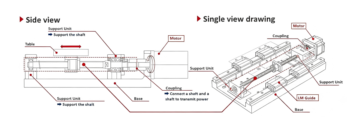
What is the coaxiality of a ball screw?
During assembly, the axes of the bearing housings at both ends of the ball screw, the screw shaft, and the motor coupling must be aligned in a straight line.
If there is a deviation in coaxiality, it means that these axes are not aligned, which will directly affect the transmission accuracy, operational smoothness, and service life of the screw.
Tools required for calibration:
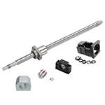
Magnetic dial indicator/micrometer, indicator base, feeler gauge, thin copper/stainless steel shims (for adjusting clearance), Allen wrench, torque wrench
Standard Test Methods
Correcting coaxiality requires accurate measurement. The standard test methods are as follows:
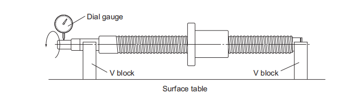
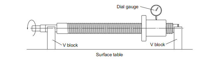
1.Radial runout of the mounting part relative to the axis of the leadscrew support:
Support the leadscrew support with a V-block. With the probe in contact with the outer diameter of the mounting part, rotate the leadscrew one revolution and measure the maximum difference in runout using a dial indicator.
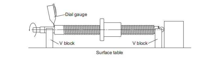
2. Radial runout of the thread groove face relative to the axis of the leadscrew support:
Support the leadscrew support with a V-block. With the probe in contact with the outer diameter of the nut, rotate the leadscrew one revolution without rotating the nut and measure the maximum difference in runout using a dial indicator.
3. Face runout of the support end face relative to the axis of the lead screw shaft support portion:
Support the leadscrew support with a V-block. With the probe in contact with the end face of the leadscrew support, rotate the leadscrew one revolution and measure the maximum difference in runout using a dial indicator.
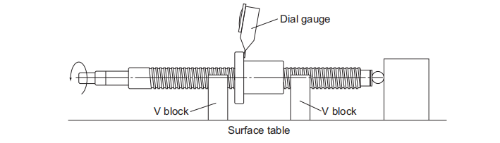
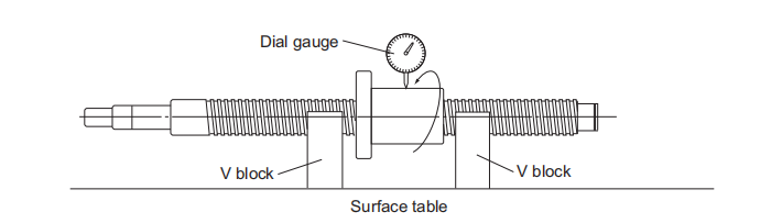
4. Circular runout of the flange mounting surface relative to the lead screw axis:
Support the outer diameter of the lead screw threaded section next to the nut using a V-block. With the probe in contact with the end face of the nut flange, rotate the lead screw and nut simultaneously for one revolution, and measure the maximum difference in runout using a dial indicator.
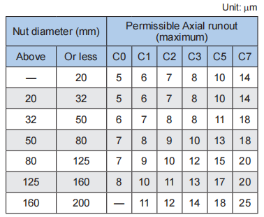
5. Radial runout of the nut outer diameter relative to the lead screw axis:
Support the outer diameter of the lead screw threaded section next to the nut using a V-block. With the probe in contact with the outer diameter of the nut, rotate the nut one revolution without rotating the lead screw, and measure the maximum difference in runout using a dial indicator.
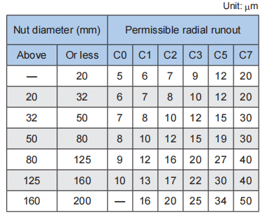
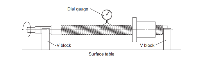
6. Total radial runout of the outer diameter of the lead screw section relative to the axis of the lead screw shaft support:
Support the lead screw support using a V-block. With the probe in contact with the outer diameter of the lead screw, rotate the lead screw one revolution, and measure the runout at multiple points along the axis using a dial indicator, recording the maximum value.
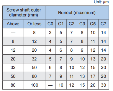
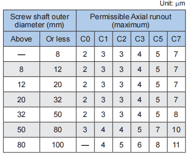
For the radial runout tolerance of the outer diameter of the lead screw relative to the axis of the lead screw shaft support, please refer to JIS B 1192 (ISO 3408).
For excessive runout of the flange mounting surface: Check if the flange connection surface is flat, or use thin shims for fine adjustment.
For excessive runout of the nut outer diameter: Adjust the mounting position of the bearing housing or nut housing, and repair the locating surface if necessary.
Re-measurement Confirmation
After each adjustment, remeasure according to the standard method until all relevant runout and parallelism meet the limits of the corresponding tolerance table.
Ball screw coaxiality calibration is a fundamental yet crucial installation task. Most problems with ball screws, such as overheating, abnormal noise, jamming, and short lifespan, originate here.
By following the process of “coarse alignment → dial gauge fine-tuning → diagonal locking → retesting and acceptance,” and strictly controlling runout error, lateral forces can be eliminated structurally, ensuring long-term stable operation of the ball screw.