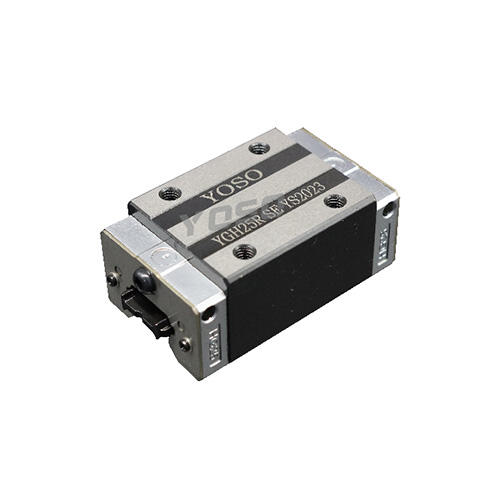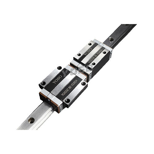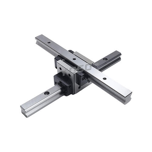
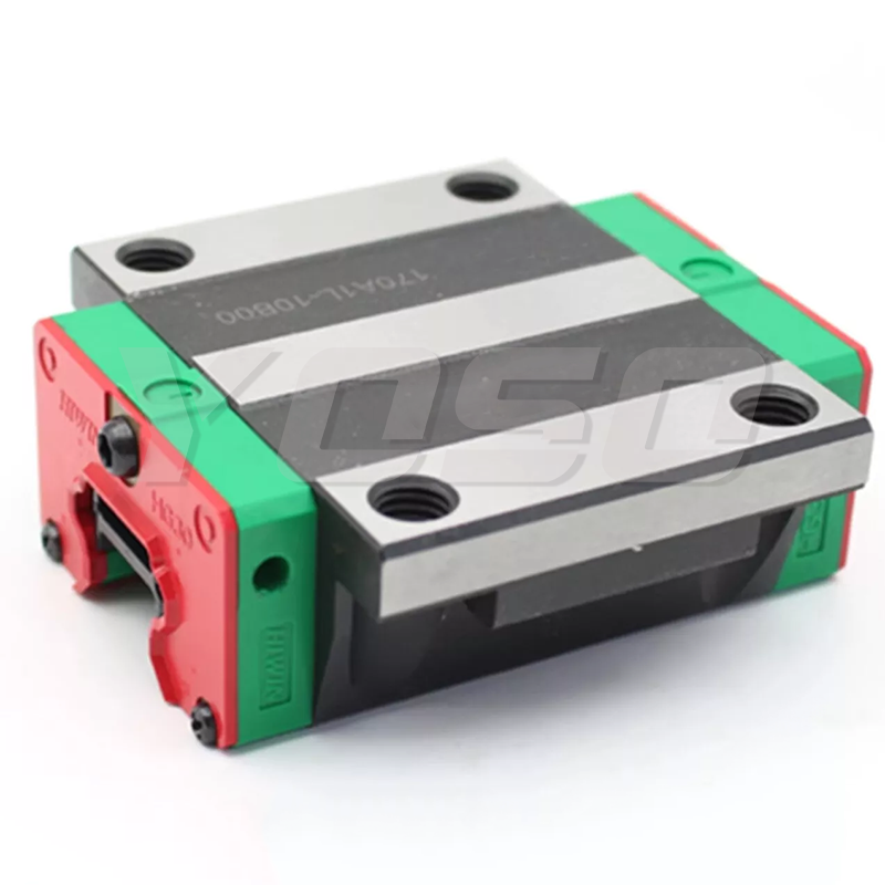


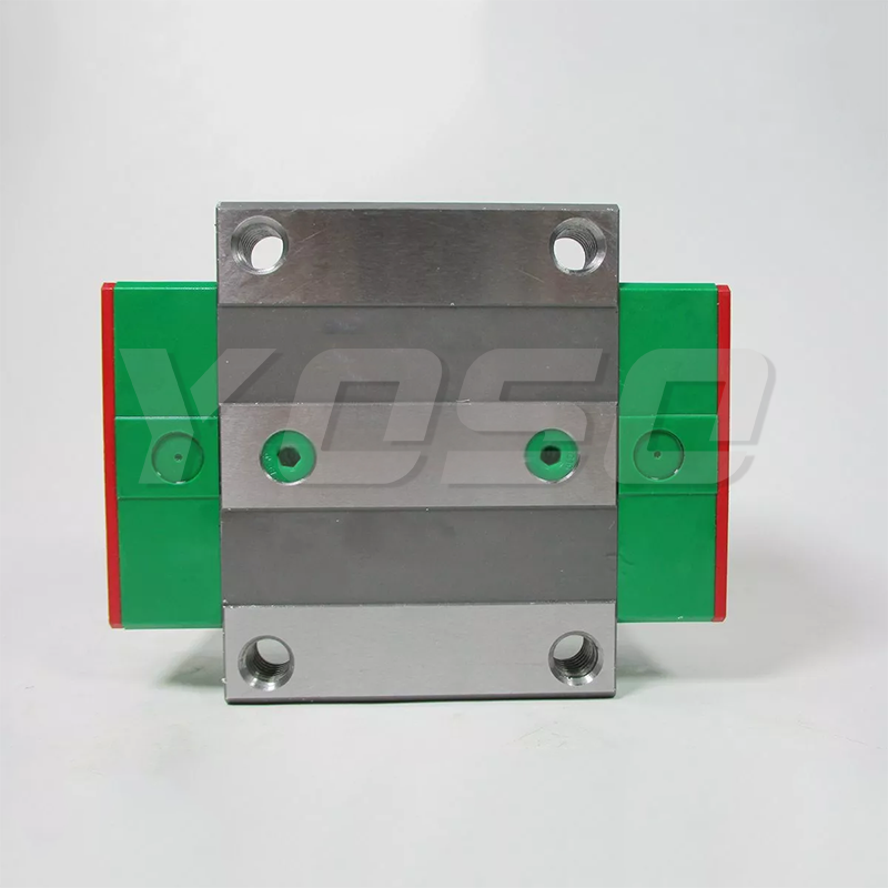

HIWIN RGW35HC is a linear guide that uses rollers instead of balls to achieve ultra-high rigidity and ultra-high load capacity. Since the rollers, guides and sliders are in linear contact, deformation is small even under high loads.
HIWIN RGW35HC linear guides also have four-way high rigidity and ultra-heavy load capacity. High rigidity significantly improves processing accuracy and meets high-precision requirements. Ultra-high load capacity ensures a long service life and is suitable for equipment that requires high rigidity, such as high-speed machine tools and FA industrial machinery.
Features
Optimized design
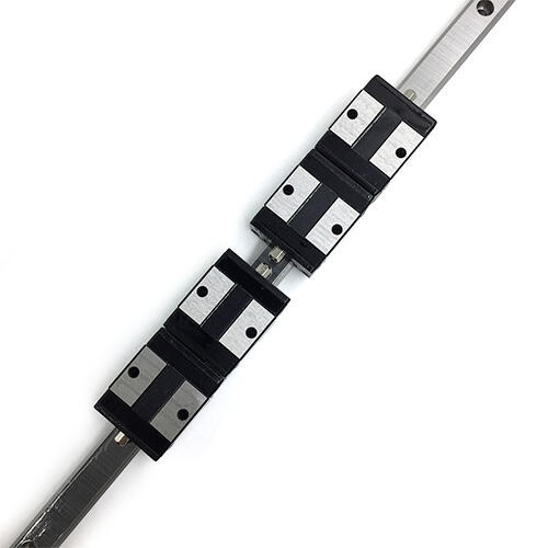
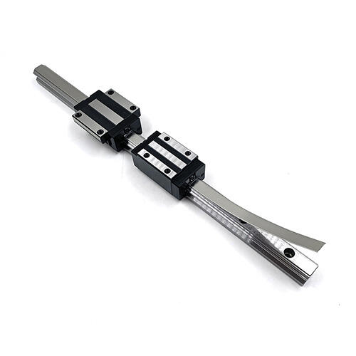
The HIWIN RGW35HC linear guides circulation system has been patented in many countries around the world for its smooth and endless circulation of rollers. The optimized structure of the slider and rail is designed by using advanced finite element method (FEM) to analyze the structural load stress.
Four-way ultra-high rigidity
In the RG series, the rollers, guides and sliders are all in line contact, so even with high loads, deformation is small. This significantly improves the rigidity of the HIWIN RGW35HC linear guides and maintains high-precision processing.
HIWIN model RGW15CC RGW20CC RGW2DHC RGW25CC RGW25HC RGW30CC RGW30HC RGW35CC RGW35HC RGW45CC RGW45HC RGW55CC RGW55HC RGW65CC RGW65HC

| Model No | Dimensions of Assembly (mm) |
Dimensions of Block (mm) | Dimensions of Rail (mm) | Mounting Bolt for Rail |
Basic Dynamic Load Rating |
Basic Static Load Rating |
Static Rated Moment |
Weight | |||||||||||||||||||||||||
| Mg
kN-m |
Mp
kN-m |
My
kN-m |
Block
kg |
Rail
kg/m |
|||||||||||||||||||||||||||||
| H | H₁ | N | W | B | B₁ | C | C₁ | L₁ | L | K₁ | K₂ | G | M | T | T₁ | H₂ | H₃ | Hg | D | h | d | P | E | (mm) | C(kN) | C₀ (kN) | |||||||
| RGW35CC | 48 | 6.5 | 33 | 100 | 82 | 9 | 62 | 52 | 79
106.5 |
124 | 16.5 | 10 | 12 | M10 | 12 | 13 | 9 | 12.6 | 34 | 30.2 | 14 | 12 | 9 | 40 | 20 | M8x25 | 57.9 | 105.2 | 2.17 | 1.44 | 1.44 | 1.75 | 6.06 |
| RGW35HC | 151.5 | 30.25 | 73.1 | 142 | 2.93 | 2.6 | 2.6 | 2.40 | |||||||||||||||||||||||||
| RGW45CC | 60 | 8 | 37.5 | 120 | 100 | 10 | 80 | 60 | 106 | 153.2 | 21 | 10 | 12.9 | M12 | 14 | 15 | 10 | 14 | 45 | 38 | 20 | 17 | 14 | 52.5 | 22.5 | M12x35 | 92.6 | 178.8 | 4.52 | 3.05 | 3.05 | 3.43 | 9.97 |
| RGW45HC | 139.8 | 187 | 37.9 | 116 | 230.9 | 6.33 | 5.47 | 5.47 | 4.57 | ||||||||||||||||||||||||
| RGW55CC | 70 | 10 | 43.5 | 140 | 116 | 12 | 95 | 70 | 125.5
173.8 |
183.7
232 |
27.75
51.9 |
12.5 | 12.9 | M14 | 16 | 17 | 12 | 17.5 | 53 | 44 | 23 | 20 | 16 | 60 | 30 | M14x45 | 130.5 | 252 | 8.01 | 5.4 | 5.4 | 5.43 | 13.98 |
| RGW55HC | 167.8 | 348 | 11.15 | 10.25 | 10.25 | 7.61 | |||||||||||||||||||||||||||
| RGW65CC
RGW65HC |
90 | 12 | 53.5 | 170 | 142 | 14 | 110 | 82 | 160
223 |
232
295 |
40.8
72.3 |
15.8 | 12.9 | M16 | 22 | 23 | 15 | 15 | 63 | 53 | 26 | 22 | 18 | 75 | M16x50 | 213 | 411.6 | 16.20 | 11.5s | 11.59 | 11.63 | 20.22 | |
| 275.3 | 572.7 | 22.55 22.17 | 22.17 | 16.58 | |||||||||||||||||||||||||||||
Subscribe to our newsletter for daily new and updates
Shanghai, China
YOSOmachinery
Copyright © Jingpeng Machinery&Equipment(Shanghai) Co.,Ltd All Rights Reserved
 EN
EN
 AR
AR
 BG
BG
 CS
CS
 DA
DA
 NL
NL
 FI
FI
 FR
FR
 DE
DE
 EL
EL
 HI
HI
 IT
IT
 JA
JA
 KO
KO
 NO
NO
 PL
PL
 PT
PT
 RU
RU
 ES
ES
 SV
SV
 TL
TL
 ID
ID
 UK
UK
 VI
VI
 HU
HU
 TH
TH
 TR
TR
 FA
FA
 AF
AF
 MS
MS
 SW
SW
 GA
GA
 CY
CY
 BE
BE
 KA
KA
 LA
LA
 MY
MY
 TG
TG
 UZ
UZ